Hi Mike,
3 seconds is normally plenty to capture the behavior of your machine. Is it taking longer than 1.5 seconds to accelerate to speed?
Maybe post your Motion Profile Settings and a Plot of a large move.
Regards
TK
| Group: DynoMotion |
Message: 5593 |
From: Michael Rosenfield |
Date: 8/22/2012 |
| Subject: Re: Following Error |
Here is that info.
| Group: DynoMotion |
Message: 5595 |
From: Tom Kerekes |
Date: 8/22/2012 |
| Subject: Re: Following Error [6 Attachments] |
Hi Mike,
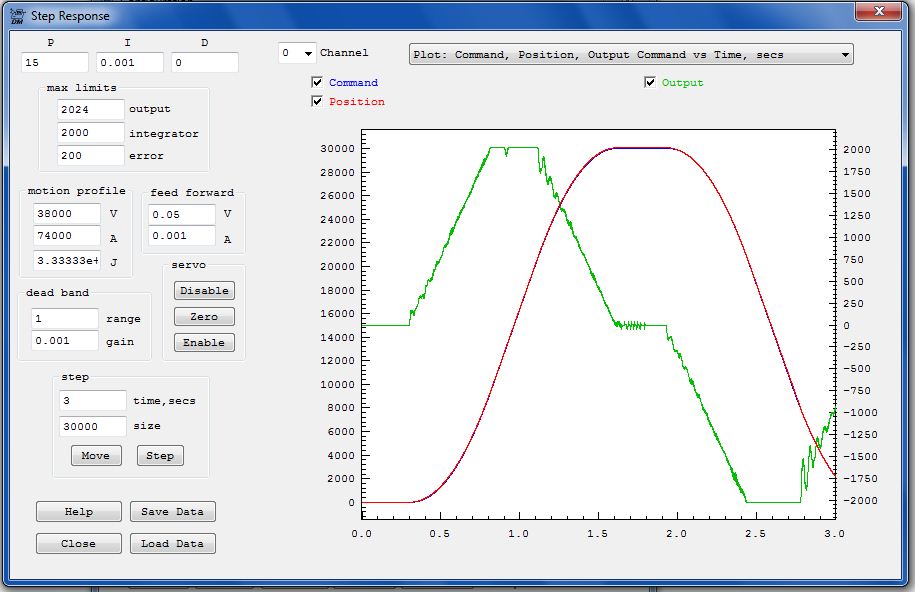
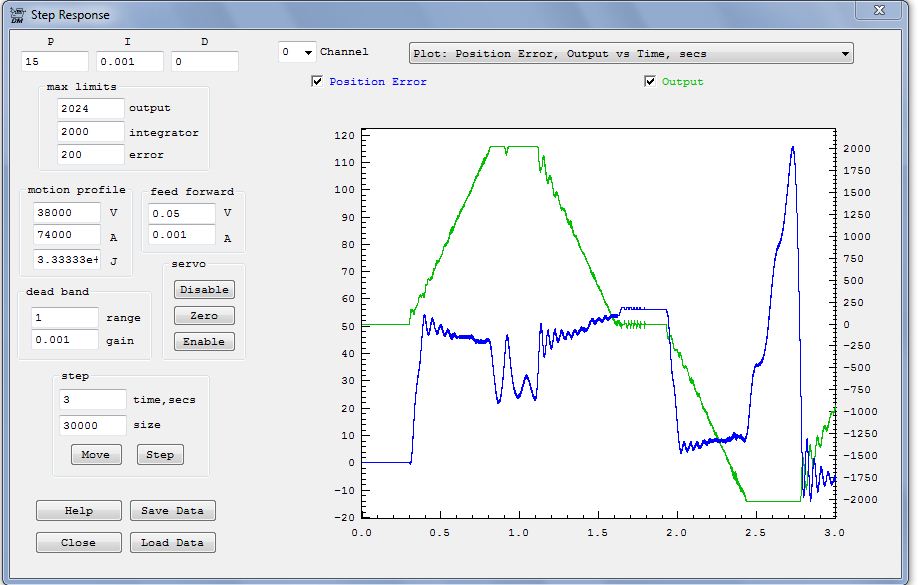
It should be clear from the plots what is going on - I'm surprised you don't see it :}
When making large moves that get up to your max allowed speed (38000cnts/sec) the Output (green plot - right axis) is right at your max allowed output setting (2024 DAC counts).
This is like having a car with the gas all the way to the floor capable of going ~100mph trying to stay next to a target that accelerates to and maintains exactly 100mph. You are sort of able to do it until there is some headwind. In that case even with the pedal to the floor you can only go 99mph and you start falling behind (following error grows). See about the 2.5sec mark on your first plot.
You must allow some reasonable margin
between your max commanded velocity and the max possible speed of your system.
Shorter moves are always ok because there isn't distance enough to even get up to full speed.
The KanalogDACs can go to +/-2047 counts. Not sure why you are limiting them to 2024 counts. Changing the Max Output Limit to 2047 will give you about 1% more speed. That might be enough to do it but that still seems pretty marginal.
There might be some gain setting in your amplifier that you could turn up to allow a full 10V input to generate a higher physical speed.
Otherwise you will need to reduce your max allowed speed to something like 35000cnts/sec.
HTH
TK
From: Michael Rosenfield <mrosenfield@...>
To: dynomotion@yahoogroups.com
Sent: Wednesday, August 22, 2012 6:33 PM
Subject: RE: [DynoMotion] Following Error [6 Attachments]
Here is that info.
| Group: DynoMotion |
Message: 5596 |
From: Michael Rosenfield |
Date: 8/22/2012 |
| Subject: Re: Following Error |
Thanks, Tom. Well, I see it now that you've explained it. This all makes sense. I'll play with it over the next few days. I have no idea where the 2024 came from - it used to be 2047. The amps are maxed out; the limit is that the current power supply is 95 V. I was going to try to increase this, but haven't gotten to that yet. Michael
| Group: DynoMotion |
Message: 5598 |
From: Michael Rosenfield |
Date: 8/23/2012 |
| Subject: Re: Following Error |
Tom, I changed the max output to 2047 and the max v to 36000 and it is working fine. The FE doesn't spike anymore on the move. in comparing the new settings to the old settings, I noticed a minor difference in the filter constants. Is there a way to work backwards from filter constants to type of filter and freq? the filter screen doesn't display this info from stored values. thanks again for all your help! michael
To: DynoMotion@yahoogroups.com From: tk@... Date: Wed, 22 Aug 2012 22:31:14 -0700 Subject: Re: [DynoMotion] Following Error
Hi Mike,
It should be clear from the plots what is going on - I'm surprised you don't see it :}
When making large moves that get up to your max allowed speed (38000cnts/sec) the Output (green plot - right axis) is right at your max allowed output setting (2024 DAC counts).
This is like having a car with the gas all the way to the floor capable of going ~100mph trying to stay next to a target that accelerates to and maintains exactly 100mph. You are sort of able to do it until there is some headwind. In that case even with the pedal to the floor you can only go 99mph and you start falling behind (following error grows). See about the 2.5sec mark on your first plot.
You must allow some reasonable margin
between your max commanded velocity and the max possible speed of your system.
Shorter moves are always ok because there isn't distance enough to even get up to full speed.
The KanalogDACs can go to +/-2047 counts. Not sure why you are limiting them to 2024 counts. Changing the Max Output Limit to 2047 will give you about 1% more speed. That might be enough to do it but that still seems pretty marginal.
There might be some gain setting in your amplifier that you could turn up to allow a full 10V input to generate a higher physical speed.
Otherwise you will need to reduce your max allowed speed to something like 35000cnts/sec.
HTH
TK
From: Michael Rosenfield <mrosenfield@...>
To: dynomotion@yahoogroups.com
Sent: Wednesday, August 22, 2012 6:33 PM
Subject: RE: [DynoMotion] Following Error [6 Attachments]
Here is that info.
| Group: DynoMotion |
Message: 5599 |
From: Tom Kerekes |
Date: 8/23/2012 |
| Subject: Re: Following Error |
Hi Mike,
I'm glad it is working now.
Regarding the filters: There isn't a way to go backwards from the Z-domain to the Frequency domain. All KFLOP
cares about is the Z-domain. You need to keep track of what was used to compute the Z-domain coefficients. The only suggestion I have to recover them is to use trial and error until you get values that match. The values might be still in the screen cells or possibly in your previous version if that was the Version used to compute them.
Regards TK
From: Michael Rosenfield <mrosenfield@...>
To: dynomotion@yahoogroups.com
Sent: Thursday, August 23, 2012 8:24 AM
Subject: RE: [DynoMotion] Following Error
Tom, I changed the max output to 2047 and the max v to 36000 and it is working fine. The FE doesn't spike anymore on the move. in comparing the new settings to the old settings, I noticed a minor difference in the filter constants. Is there a way to work backwards from filter constants to type of filter and freq? the filter screen doesn't display this info from stored values. thanks again for all your help! michael
To: DynoMotion@yahoogroups.com From: tk@... Date: Wed, 22 Aug 2012 22:31:14 -0700 Subject: Re: [DynoMotion] Following Error
Hi Mike,
It should be clear from the plots what is going on - I'm surprised you don't see it :}
When making large moves that get up to your max allowed speed (38000cnts/sec) the Output (green plot - right axis) is right at your max allowed output setting (2024 DAC counts).
This is like having a car with the gas all the way to the floor capable of going ~100mph trying to stay next to a target that accelerates to and maintains exactly 100mph. You are sort of able to do it until there is some headwind. In that case even with the pedal to the floor you can only go 99mph and you start falling behind (following error grows). See about the 2.5sec mark on your first
plot.
You must allow some reasonable margin
between your max commanded velocity and the max possible speed of your system.
Shorter moves are always ok because there isn't distance enough to even get up to full speed.
The KanalogDACs can go to +/-2047 counts. Not sure why you are limiting them to 2024 counts. Changing the Max Output Limit to 2047 will give you about 1% more speed. That might be enough to do it but that still seems pretty marginal.
There might be some gain setting in your amplifier that you could turn up to allow a full 10V input to generate a higher physical speed.
Otherwise you will need to reduce your max allowed speed to something like 35000cnts/sec.
HTH
TK
From: Michael Rosenfield <mrosenfield@...>
To: dynomotion@yahoogroups.com
Sent: Wednesday, August 22, 2012 6:33 PM
Subject: RE: [DynoMotion] Following Error [6 Attachments]
Here is that info.
| Group: DynoMotion |
Message: 5600 |
From: Lee Studley |
Date: 8/23/2012 |
| Subject: Re: Following Error |
Tom,
I changed the max output to 2047 and the max v to 36000 and it
is working fine. The FE doesn't spike anymore on the move.
in comparing the new settings to the old settings, I noticed a
minor difference in the filter constants. Is there a way to work
backwards from filter constants to type of filter and freq?
the filter screen doesn't display this info from stored values.
thanks again for all your help!
michael
|
|
| Group: DynoMotion |
Message: 5602 |
From: Tom Kerekes |
Date: 8/23/2012 |
| Subject: Re: Following Error |
BTW the Bode Plot Screen will plot the magnitude and phase response of the filters also. It plots the total compensation of all 3 filters plus the PID. So to see a single filter clear the other filters to a gain of 1 (B0=1) and P=1, D=0, I=0.
Regards
TK
| Group: DynoMotion |
Message: 5603 |
From: Michael Rosenfield |
Date: 8/23/2012 |
| Subject: Re: Following Error |
Thanks, guys! I'll check both those out. Michael
| Group: DynoMotion |
Message: 11066 |
From: melling_paul |
Date: 2/12/2015 |
| Subject: Following Error |
I am hoping someone can help me with an issue I have been having with my kflop/kanalog. Running closed loop on my mill with gecko drivers and glass scales. I keep getting following errors when running gcode in kmotion. When I set the max following error low, to maybe 50, it runs for a little while, but stops. When I set it up a lot higher to, 500 or 1000, it runs longer. But still stops with a following error. Is error somehow accumulating somewhere? I am just not sure where to go next to try to fix this. Thanks, Paul |
|
| Group: DynoMotion |
Message: 11067 |
From: Hardy Family |
Date: 2/12/2015 |
| Subject: Re: Following Error |
By coincidence, I am setting up exactly the same arrangement. What are your PID parameters? For closed loop stepper, you probably want zero for all except "I", which should start at about 0.001 and increase until it runs rough during a move. Also, if your input (encoder) "gain" is not correct, then at some point the following error will build up, depending on how far the axis is moved from its "reference" position.
Regards, AB |
|
| Group: DynoMotion |
Message: 11068 |
From: melling_paul |
Date: 2/12/2015 |
| Subject: Re: Following Error |
P=0,i=.01,d=0. Just retuned my drivers with a scope, it is really smooth. I recalculated my input gain a couple times. I can run the length of all axis without a problem and the step response curve matches almost exactly. 16380 is about how many steps per inch I am using, so 500 is about .03" seem like a lot to be off. When running a program that just does a 1" circle over and over it will run for 10 or 15 minutes, before the error shows up, less time when the following error is set lower. Do any of the other numbers make a difference? like max limits or feed forward? I don't fully understand all the settings.
Also, running slower with lower acceleration seems to make it run longer before it errors out, 2.5in/s and 10in/s^2, is what I have been using, it'll run when it's high that, the errors just show up sooner. Paul |
|
| Group: DynoMotion |
Message: 11071 |
From: Hardy Family |
Date: 2/12/2015 |
| Subject: Re: Following Error |
In theory, with a step motor, the following error should be set to the number of steps in 180 degrees of (electrical) rotation. For a 200 step per rev motor, that would be typically 20 steps (with 10x microstepping), although in practice you probably want about 50 to account for leadscrew error etc. That's what I'm using, with geckodrives, and the motors are running pretty close to the limit at 212ipm. (90,000 steps/sec - they stall if I push it to 95,000).
What you might try, to track down the problem, is set I=0 to temporarily defeat the feedback. Set the error limit quite high (like 50000), and keep an eye on the Axis screen when you are running the circle program. Feed hold it every now and again, then check on the axis screen that the encoder and command position numbers are fairly close. There's probably a way for KMotion to keep track of the max error for you (not sure what it is myself), but eyeballing it should work. Regards, AB |
|
| Group: DynoMotion |
Message: 11072 |
From: Hardy Family |
Date: 2/12/2015 |
| Subject: Re: Following Error |
By the way, I had a similar problem to what you are seeing when I first started working with the linear scale. It turned out the leadscrew bearing wasn't fully tightened, and was being held by friction alone (explains some dodgy parts I made). Naturally, the axial slippage can cause a large discrepancy between the step motor position and the feedback from the encoder.
So make sure everything is hunky dory. Also, make sure the encoder signal is clean, and installed correctly. If there's electrical noise, or it drops out occasionally, then that will also cause following errors. Regards, AB |
|
| Group: DynoMotion |
Message: 11073 |
From: melling_paul |
Date: 2/12/2015 |
| Subject: Re: Following Error |
Thank you so much for the info, so if I have my gecko connected to my servo motor with 16380 steps per inch and a 10x reduction. Does that mean my following error should be set at about 800?
Watching the axis screen helped a lot, I just changed the step response settings till it was as close as I could get it. Then ran my circle program, after 2000 lines it was off by 8 at the most. I am not exactly sure which setting did it, but I think lowing my jerk helped. Thanks you so much for the help. I'll be trying a few more long test runs over the next few days. Thanks, Paul |
|
| Group: DynoMotion |
Message: 11074 |
From: Hardy Family |
Date: 2/12/2015 |
| Subject: Re: Following Error |
Assuming your motor does 1 rev per 2000 steps (from the Kmotion point of view), then 16380 steps is 8.19 motor revs. That's an odd ratio. Are you sure it's correct? What is your leadscrew pitch, and what gear ratio between the motor and leadscrew?
If you are running nothing but a smooth circle, then jerk should not have much affect because accelerations will be small and slowly varying. A better test would be to run 1 inch squares; that would stress test acceleration and jerk. The ultimate test, for real confidence with the machine, would be to run continuous back-and-forth rapids (g0) between the physical limits of each axis, or just short of this. Like this (assuming the machine is zerod at the positive limit of each axis): g0 x-10 y-5 z-6 g0 x0 y0 z0 (obviously, change the distances in the first line to suit). It is my understanding (and I may not be entirely correct about the Kmotion algorithm) that the following-error in a closed loop stepper setup should be M+B+E where M is 20 steps of allowance for the step motor itself, B is the worst-case backlash measured in steps, and E is the worst leadscrew error over the entire range of motion. The leadscrew error is the difference between the encoder count, and the actual number of steps supplied to the motor, assuming they were set equal at some point. This assumes that there is no permanent lost motion anywhere. For example, if there was a v-belt (friction) drive in the drive chain, then there would no longer be a fixed ratio of motion. You could still run such a system accurately, but would need an unlimited following-error. Regards, AB |
|
| Group: DynoMotion |
Message: 11076 |
From: melling_paul |
Date: 2/13/2015 |
| Subject: Re: Following Error |
It's a 8x reduction, brain fart, 2048, counts per rev encoder, so its 16384 per inch. My scales are 5 micron, or 5080 per inch making my input gain 3.2251968503937007874015748031496. That seems to be working pretty well for me. Does that look correct?
I've also been running rapids back and forth from .1 inch to max travel on each axis. I am going to recalculate my max following error using the info you supplied, that makes a lot of sense to do it that way. Thanks for the info. It really helped, Paul |
|
| Group: DynoMotion |
Message: 11077 |
From: Tom Kerekes |
Date: 2/13/2015 |
| Subject: Re: Following Error |
Hi Paul,
To test if the Encoder Input Gain is set properly to make the encoder counts match motor steps perform a large open loop move on the step response screen and observe if the commanded and measured positions match closely within mechanical tolerances.
I think there is some misconception on how Max Output and Max Following Error in KFLOP work. Assume for the sake of discussion that some Motor Drive microstep pulses are somehow being lost. In this case the closed loop control will detect that the encoder has not moved to the correct place and will increase the output to make a correction, which will generate more step pulses until the encoder reads at the correct position, and the error is zero. In this way the following error will remain zero. Even if more and more step pulses are lost, the following error will remain zero until the point where the Servo Output reaches the Max Allowed Output. At this point the servo will no longer correct for errors and as more microstep pulses are lost the following error will begin to grow. Eventually the following error will grow until the Max Following Error is reached, and at that point the axes will be disabled and halt.
In a well working system electrical step pulses or electrical encoder counts should never be lost or gained. The Servo should only need to correct for small mechanical errors that should never exceed a small value and never keep growing continuously. If the necessary Servo Output Correction continuously grows without bound it indicates loss or noise on the step pulses (drive does not receive the correct distance to move) or loss of encoder counts (encoder does not measure the position correctly). This assumes there is no mechanical "slippage" of a belt or pulley connection. To determine which is being lost (step pulses or encoder counts) you can move back to your original position. If the axis returns to the correct physical position then the encoder is working correctly.
Besides noise a common problem to cause lost step pulses is to not have enough Direction Setup Time for your drives. In that case sometimes after a direction change the drive will misinterpret the step to be in the wrong/previous direction. Closed loop control can exacerbate this effect greatly as small back and forth dithering motions (many direction changes) may be necessary to hold zero error. If this is your problem try inverting the polarity of the step pulses so the drive steps in the trailing edge of the step pulse rather than the leading edge. Increasing the pulse length will also provide more time.
HTH Regards TK
| Group: DynoMotion |
Message: 11109 |
From: Tom Kerekes |
Date: 2/18/2015 |
| Subject: Re: Following Error |
Hi Paul,
You can set the Polarity and Pulse length by setting a register in KFLOP's FPGA. See:
Let me know if you have questions.
Regards TK
| Group: DynoMotion |
Message: 12274 |
From: cnc_machines |
Date: 9/17/2015 |
| Subject: Following Error |
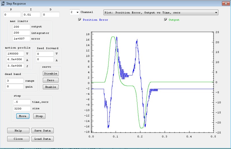
Tom, I cant seem to figure out what I am doing wrong to give me following errors. I am running CL steppers with the Kstep. I am able to use the step response screen to set Velocity, Acceleration, and Jerk so that my max error is less than 20 counts - tested making very short and also long moves. I then set my max following error to 50 and upload to my INIT file. The image has parameters for this axis. While my INIT file is running, I open another thread to do move the machine to several positions to home a blade. Move(2, -3200); while(!CheckDone(2));
This always gives me a following error. I thought that this would limit
speed to the parameters set in the INIT file? Is this not the case? Any idea why this is happening?
I have never played with the filter settings with these steppers - could this have something to do with my problems? Should I be setting any filters when running CL steppers?
Thanks again for your help!
Scott
|
|
|
|
| Group: DynoMotion |
Message: 12279 |
From: Tom Kerekes |
Date: 9/18/2015 |
| Subject: Re: Following Error [1 Attachment] |
Hi Scott,
You are correct that the Move() function called from a C Program should move in exactly the same manner as a Move on the Step Response Screen if the Axis Parameters are all set to the same values when the moves are made.
Are you sure the Axis Parameters on the Screens (Config/Flash, Step Response, and Filters) are all set to the exact same values as the INIT C Program?
You stated that you "upload to my INIT file".
That would be the wrong thing to do.
Once you have all the Settings on the Screens working well you should "Export All to Open C Program" to put the settings into your INIT C Program.
HTH Regards TK
| Group: DynoMotion |
Message: 12286 |
From: cnc_machines |
Date: 9/21/2015 |
| Subject: Re: Following Error |
Tom, I did click on export parameters to the open C program. Still trying to work through this and have noticed a few more questions. - A G00 move in KMotionCNC doesn't seem to go nearly as fast as moving the axis directly in a C program (Move(2, -3200).
- A G00 move also appears to be doing coordinated motion. I thought this would drive each axis to position at its max speed? It appears to respond more like a G01 where all of the axis are synchronized to arrive at the same time. Do you know why this is the case?
- If I turn up the feed override to 2 on KMotion CNC it appears closer to the speed that I get in the step response screen. Also very surprising that I dont get following errors when I turn it so fast as I have pushed the limits in the step response screen.
It seems like I must be missing something. I also wanted to ask about how to set the IIR filters for a CL stepper with the KStep. Do you have any suggestions on how to set them?
I noticed the following code in the example KStep program and am not sure what it does. I have 5 machines that are mechanically identical. I want to make sure I have them all set up correctly.
// Add a small amount of Coordinated Motion Path smoothing if desired
// Tau = 0.001; // seconds for Low Pass Filter Time Constant
// KLP = exp(-TIMEBASE/Tau);
KLP=0; // force to 0 to disable
// printf("Tau=%f KLP=%f\n",Tau,KLP);
Thanks,
Scott
|
|
| Group: DynoMotion |
Message: 12288 |
From: Tom Kerekes |
Date: 9/21/2015 |
| Subject: Re: Following Error |
Hi Scott,
A single Axis Move as a Rapid in KMotionCNC should move exactly the same as a C Program Move of the same axis. So something must be wrong.
Describing a clear, complete, simple sequence to demonstrate the issue would be helpful for us.
Exporting parameters to a C Program file will not in itself change axis parameters in KFLOP. The C Program must be saved/compiled/downloaded/executed to have an effect. It isn't clear if you understand this. This Flash Video may help:
To help understand things you might make dramatic reduction in speeds so that you can see if/when any changes you are making have an effect. For example you might reduce the speed such that a 5 inch move should take 20 seconds (0.25ips).
Regarding question #2: A G0 move does move in an interpolated manner along a straight line. Otherwise multi-axis motion paths can be somewhat unpredictable and may cause crashes. Basically one axis will always limit the Velocity, Acceleration, or Jerk and the other axes will be reduced to keep the same pace.
Regarding question #3: What Version are you using? Did you mean to say Rapid Override?
IIR Filters are fairly complex. Usually with closed loop Step/Dir a Low Pass filter can be helpful as shown here:
The KLP parameter provides low pass filtering/smoothing of the coordinated motion trajectory and can be very helpful to reduce Jerk. This can potentially allow faster and smoother motion. It does cause the trajectory to lag slightly behind and introduces some corner rounding. For most systems a Time Constant of 1~3 milliseconds will not cause significant path errors. See the description of this here:
Regards TK
| Group: DynoMotion |
Message: 12290 |
From: cnc_machines |
Date: 9/21/2015 |
| Subject: Re: Following Error |
|
Tom,
Thanks for the reply. I am aware that I need to save and compile the program before it is actually loaded. I was however unaware that a G00 did any coordinated motion at all. I thought it drove all axises at max velocity to their final destinations. I think I was perceiving a slowdown because one of my axises is limiting the speed. One of them I hadnt tuned very carfully was causing a bottleneck.
I will need to take some time reading through the filter examples you sent. Will come back with questions if needed.
Scott
|
|
| Group: DynoMotion |
Message: 13314 |
From: cnc_machines |
Date: 5/31/2016 |
| Subject: Following Error |
Tom,
I am having an issue where I have 3 axis using the coordinated motion planner, and a 4th which doesnt. I would like a following error on the 4th axis to fault the CNC program being run on the other three.
Can you think of a simple way to do this, maybe a simple line or two in the INIT file?
Thanks,
Scott |
|
| Group: DynoMotion |
Message: 13317 |
From: Tom Kerekes |
Date: 5/31/2016 |
| Subject: Re: Following Error |
Hi Scott,
Look at the example watchenables_disableall.c
See if you can expand it from 3 to 4 axes.
I'm thinking if any of your 4 axes become disabled they should
all be disabled.
Regards
TK
Tom,
I am having an issue where I have 3 axis using the
coordinated motion planner, and a 4th which doesnt. I
would like a following error on the 4th axis to fault the
CNC program being run on the other three.
Can you think of a simple way to do this, maybe a simple
line or two in the INIT file?
Thanks,
Scott
|
|
| Group: DynoMotion |
Message: 13319 |
From: cnc_machines |
Date: 5/31/2016 |
| Subject: Re: Following Error |
|
Thanks! I think that will do it.
|
|
| | | | | | | | | | | | | | | | | | | | | | | |
.JPG)